Monday 8 September 2014

Introducing Elvis


Elvis is a 6-axis robotic arm the size of a human arm, built from off the shelf electronics and laser-cut acrylic pieces, and is directly driven from Rhino + Grasshopper. This is the official introduction of Elvis 1.0.


Elvis is open source and shared under a GNU GPL v3.0 licence so you can download everything required to build and use it from its GitHub page. It is very much a work-in-progress, and a lot can be improved. Included in there is a basic template for an end-effector, you can build on top of that to suit whatever it is you want to do with it. You can also modify the basic design of the robot itself to suit your requirement.

Elvis Mission Control in Grasshopper

Why Elvis?


Robotics is an interesting area of design/fabrication research, and recent developments by the likes of ETH ZurichICD Stuttgart, Bot & Dolly, TU Delft and numerous others have created excitement and spurred curiosity around the interesting potential robotics has in design and architecture. But anyone who has ever setup a Kuka/ABB/etc. knows that programming one is no easy task. They're extremely capable, precise and sophisticated in what they can do, but they can take a while to setup making it difficult to test draft ideas and prototype in quick iteration. And that is assuming you are lucky enough to have ready access to a robotic arm -- which most designers don't.

Elvis was conceived to fit this need. It's small, light and portable, and is meant for quick prototyping & iteration -- hence the direct control from within Grasshopper. It is not meant to replace an industrial-grade arm: it is not as precise or as fast, it costs roughly 5% of the cheapest desktop industrial arm available, and it takes a person about 2-3 days to put one together.
 
Elvis's version of "Hello world" 

Technical Details


DOF/Axis: 6
Motors: 8 x Servos, Dynamixel AX-12A
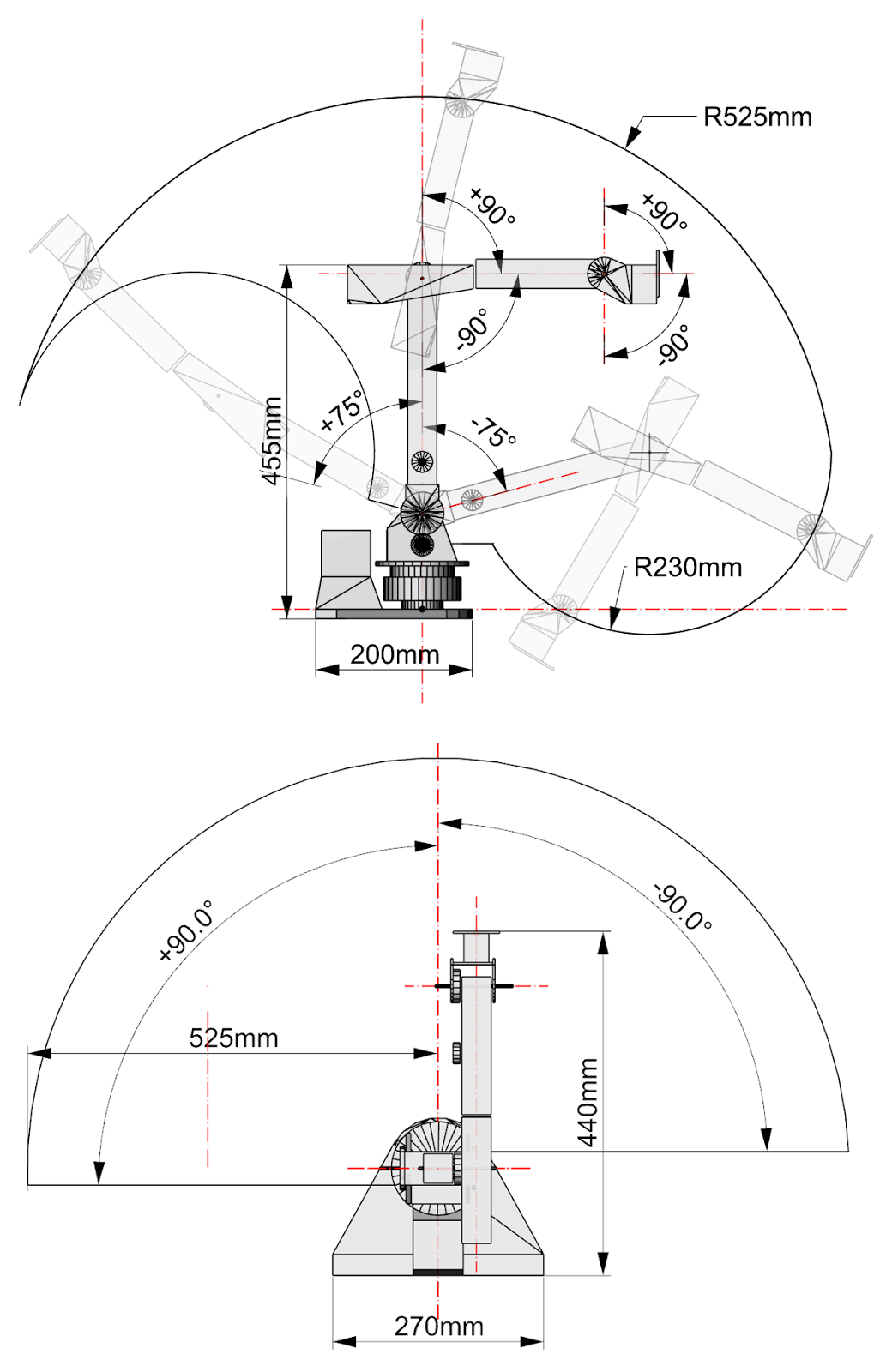
Range: ~525mm for wrist Centre (diagram below explains in detail)
Cost: £480 (UK). Presumably cheaper in the US/Asia. Detailed breakdown here.
IK Solver: Trigonometric
Wrist Type: Spherical


Future Development


Broadly speaking, the precision of the arm needs to be significantly improved. As of now, there is backlash in the system caused by the servos, and there is also flex in the materials used to built the arm itself. Geometric changes can substantially reduce the material flex leading to improved accuracy. Eventually backlash could be reduced through more appropriate hardware.

Elvis uses servos that are capable of reading their positions, so within a tolerance, the arm already "knows" where it is. This could easily be used as a forward kinematic system to digitally read positions in space and generate gcode for larger arms, similar to the system proposed by Andrew Payne, with the added benefit of a 6th axis. A camera/leap/kinect/other sensory mechanism can be used to setup an enhanced feedback system giving it a more precise idea of where it is, where it should be or what it should do next.

There are some very good robot simulation tools available on Grasshopper such as Daniel Piker's LobsterRobots.IO's Godzilla, etc. Last I checked I was unable to use Lobster as the IK solver for Elvis because of Elvis's asymmetrical axis configuration. I haven't been able to test it with Godzilla as yet, but the intention is to make Elvis easier to use with all these fantastic tools already available.

Acknowledgements


The directors, tutors and students of AAVS Dubai and AAVS Lyon for being wonderful platforms to further the development of Elvis, and the ZHA_code bunch for the insights and stimulating conversations.

The AA Visiting School Dubai showreel about the process of building and using Elvis


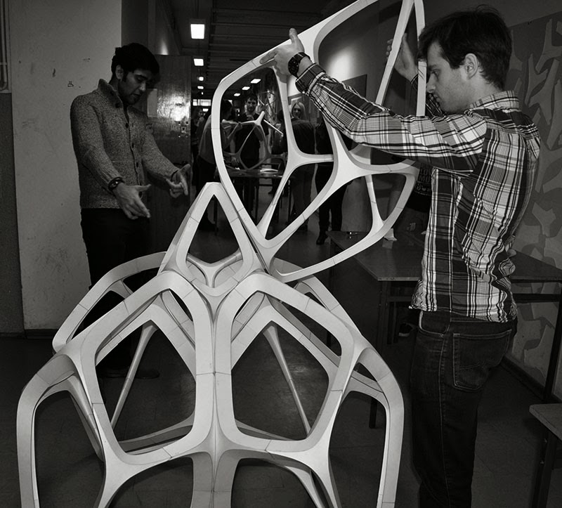
Man vs. Robot: Haider and Elvis in an 'axis-fight' at the AA Visiting School Dubai

The Grasshopper control file can compute IK for given toolpaths and directly move Elvis on those paths.

Thursday 23 January 2014

Fragile Beasts | Sculpting Paper


A short 3-day workshop at the Łódź University of Technology with a fantastic outcome. Together with 17 students, we managed to do some interesting exercises and build a 1.9m tall beast from half millimetre thick card paper. As evident in the diagrams, the beast was designed and modelled as a cluster of polyhedra, and then a series of scripts were applied to make it curved-foldable. 

Apart from how strong it was structurally (at least to support itself), there were two interesting outcomes of the workshop: In continuing the lineage of curved folding (previously here and here), this prototype proved that curved folded polyhedra can be aggregated to form more complex structures (albeit to a limited extent).

Secondly, it never fails to amaze me how nicely this shape lends itself to fabrication and quick assembly: this piece took about 5 hours of laser cutting time and a further 5 hours to fold, glue and assemble together; and all this by a group of 17 students who had never done any form of curved folding before.

Credits:
Anetta Kepczynska-Walczak | Assistant Professor, Łódź University of Technology, Poland
Sebastian Bialkowski | Doctoral Candidate, Łódź University of Technology, Poland
Suryansh Chandra | Senior Designer, ZHA | Code, London


The Design Intention

The Design Process
The LaserCut Pieces Arrive in the Studio

The Folding Assembly Line

Because Folding is so much Fun :)

Uhu it Up: Gluing the Pieces that form a single Polyhedron 

Parallel Processing: Each Polyhedron could be Assembled with a Small Team of Just 2 or 3

Completed First Polyhedron

Being a Sunday, we Hogged the Entire Corridor of our Floor to Setup our Assembly Line

Joining the first two Polyhedra

Edges Lineup Well

Some Narrow Edges Weren't Conducive to being Folded too Sharply

The Base Coming Together

The Lower Half Forming the Base and the Feet done

The Base and one of the Polyhedrons of the Crown. The Leftovers from the Laser Cutter made into Wall Art on the Left.

A Keystone Piece Locks Everything Together

Alignment Checks

SuperLight: One of the Advantages of Paper

Almost there: The Crown Being put into Place


All done: The Entire Team

Thanks to everyone involved for making this possible and finishing up with such an astonishing outcome in just 3 short days, and to the avid photographers for documenting the entire workshop and taking the pictures you see above. A special thanks to Anetta and Sebastian for all their hard work, time and working relentlessly to make sure everything went smoothly, and all the things we took for granted.

I am curious to see how long this piece stands against the brutality of moisture and curious human beings, which over time will soften and distort the paper eventually buckling and deforming.

Friday 27 September 2013

ZHA Serpentine Sackler Opening


Some photos from the opening of the ZHA Serpentine Sackler Gallery last night. A barrisol shell, super nice columns that double as light wells, well executed curved glass walls, and some very cool hand-dryers in the washrooms. Check it out if you're in London. More details and the official website here.

Kudos to ZHA, Thomas, Jens, Fabian, Torsten, and the rest of the team for pulling it off!


Saturday 31 August 2013

Automating AutoCAD


Automating production of 2D drawings from 3D data through Grasshopper. The fabricator required us to produce per-layer drawings for each panel in the structure (6 layers x 12 panels x 3 structures), and annotate the X-Y-Z coordinates of several points on each curve. And we had 3 days to do it. Thus was born this:


Pseudocode:

1. Take base geometry (generated through another process), and panel split lines (drawn manually)
2. Identify the components of geometry by tags and split them
3. Lay them out in 2D space
4. Compute necessary annotations, grid, text, keyplan, coordinate data, etc.
5. Iterating per-panel:
      a) bake all geometry associated with the panel in relevant layers using the ObjectAttributes class
      b) store the Guids of the objects baked in this run
      c) once baking of the objects in the current panel is complete, select them using the Guids stored
      d) call -Export on the Rhino command line through Rhino.RhinoApp.RunScript()
      e) watch as your windows folder populates itself with the drawings :)

Acknowledgements:

Philipp Ostermaier for the awesome key-plans in each sheet and vital contributions to the code.


Friday 30 August 2013

Building with Earth | Thin Shell Structures


AA Visiting School Lyon, Synchronised Movements 2013: A 10-day design-build workshop exploring a collaboration between digital design methods + workflows and the hands-on nature of building with earth. More details: http://lyon.aaschool.ac.uk/. This was the first of an annual series of workshops, that will contribute to furthering the research agenda every year. It's held at the Les Grands Ateliers in Villefontaine, France, which also hosts the CRATerre festival of Earthen Architecture at the same time as the workshop.

The image series below documents the design + fabrication process of a thin-shell structure built during the workshop using principles of catenary arches and minimal surfaces. There wasn't a feasible way of precisely controlling thickness: it varies from 5-10mm and its built using 4 layers of earth with two layers of loosely woven jute as reinforcement.

Credits:
Architectural Association | Christopher Pierce, Priji Balakrishnan
Zaha Hadid Architects | Marie-Perrine Plaçais, Suryansh Chandra
Stéphanie Chaltiel Architecture | Stéphanie Chaltiel
Chiara Pozzi Architecture | Chiara Pozzi
Morphogenesism | Zubin Khabazi
Les Grands Ateliers | Patrice Doat
Grenoble School of Architecture | Philipe Liveneau

Design Iterations: Mostly dictated by the size limits of the CNC machine and our ambitions.

Design Process: Polygon to CNC millable pieces

Fabrication Data for Machine: Nested in sheets and labelled

Fabrication Data for Human: Assembling the shell one pizza slice at a time.

The Machine: doing its thing..

The Machine: did its thing.

The Humans: doing their thing. The big and small things you see all around are some of the other tests and structures that we built..

Assembly complete.

Time for Fabric: This fabric is the main formwork on which the earth will be applied. The plywood is just so the fabric can take the correct shape.

One Pizza Slice at a Time: Don't go by the laughing faces, it took some serious pulling to get the fabric taut.

Undo: Going wrong meant painstakingly ripping the fabric and removing the pins.

Fabric complete.

Putting the pizza together: Each slice was assembled separately, so it took clamping/bolting to bring the shell together

Brace: The fabric was so taut that it was pulling the arches too far in.

Braced: All braces in place keeping the arches vertical. The first coat on the fabric is a stiffener, and it also makes the surface fairly rough. This helps earth stick a lot better.

Indiglo: the stiffener coat is almost complete. Halogen lamps were put inside to expedite the drying process.

Hands-on: Marie-Perrine applying the first coat of earth..

Tactile process: using hands to apply earth has a sculptor-like quality due to its tactility - a rare quality in an increasingly digital world.


First layer of earth complete.

The oven: Drying time was a big factor in a 10-day workshop with rainy weather. An army of halogen lamps and plywood sheets were used to turn the entire shell into an oven. In an ideal world one could be more eco-friendly given more time and less rain.

Coat 2 begins..

Nasty Edges: Chiara ensuring the edges get enough earth. Due to the design and planarity constraints, the edges often got too narrow to be able to apply earth properly. 

Coat 3

The Sag: As more coats were applied, previously dried up coats would also soak some moisture and get soft. This led to a bit of sagging and the inner arches started to protrude on the outside - not exactly how it was designed.

The Sag: the increasing weight of earth with each coat was starting to get concerning, as it introduce some unpredictable forces within the shell.

Demoulding Begins: The shell felt very firm upon drying and we decide to stop adding more earth to avoid increasing self-weight. Demoulding begins by cutting out all the fabric first.

Demoulding: the pizza slices seem to hold without the fabric..

Arches Off: The first external arch comes off, and for the first time we perceive how thin the shell really is - and it's anyone's guess if this will stand.

All Arches Off: All 5 external arches are out, only the 5 inside remain - those are the real challenge. We were very tempted to leave the inner arches in place to hold it up, but then it wouldn't be worthy of an experiment if we play safe.

The Show: Quite an audience is starting to gather around, as eager as us. Whether this stands or collapses, this is going to be quite a show.

Demoulding: Removing the inner arches was extremely tricky because they locked each other like keystones, and the shell had sagged around them, making it very difficult to slide them out of place.

Hacksaws and Brute Force: All kinds of crazy ideas were on the table to get these off.

Twist, Rotate, Push, Pull: After some serious cajoling, the inner arches were starting to come off. The shell shook quite a bit while we applied so much force - and we were somewhat scared that it might just collapse on us while we're still pulling these arches out.
The Smiles and the Wonder: The last half-arch remains and it's the first time we get the sense that its probably going to be able to stand on its own :)

Its Off: We take the last arch out and run.. in case it comes down.

It Stands!: The finish of the edges leaves much to be desired, and could even be fixed after demoulding but this was the last day of the workshop and we were out of time.


Pride: The structure hosted the convocation ceremony of the workshop.


Unfortunately, the shell didn't have too long a life: it needed to be moved in order to make room for other activities, and didn't survive the lateral loads imposed by the move. Oh well, such is life.


We were personally extremely impressed at the fact that it could stand at such minimal thickness, and earth did extremely well given that the design process ensured that it was mostly compression forces in the structure. The works of the BLOCK Research Group, Anna Herringer, Carl Giskes, Kinya Maruyama, and many others served as valuable precedents for us, and we thank all the great Earth Experts who constantly advised and steered us novices with just about everything. We certainly need to improve our skills at working with earth: the (very) rough edges of the structures are a testament to our novice-level skills at this.

A big thanks to everyone involved for bringing your ideas, expertise, energy, and yourselves to this fantastic workshop. A big thanks to the students and other tutors for giving us the picture that you see above.